Model Wind Turbine
Overview
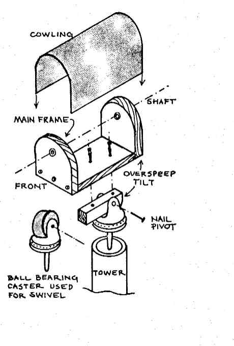
To build a small windcharger, you will need to use most of the information you have studied in this chapter. An airfoil (aerodynamic) blade such as that described in the blade section can be mounted on this machine. The main frame could also be used for experimenting with most of the other blades described earlier in this chapter. Pulleys transfer energy from the shaft to a small DC motor that acts as a generator. Overspeed control is achieved by mounting the main frame on a hinge so that the whole assembly can swing to a vertical position in high winds. A spring may be added to adjust the speed at that this tilt occurs. With this basic set-up you can continue to add refinements such as slip rings, manual turn-off and ball bearings.
MATERIALS
1' x 5"of 3/4" pine board
7" of 3/32" rod
2" of 3/32" I.D. brass tubing or ball bearings
Small DC motor
A 10'' of sheet metal or 1/8" plexiglass for cowling
1) ball bearing coaster wheel swivel
2' of 3/8" dowel
8''x l 8" x l/8" plywood or plexiglass for tail
6" of 1" x l " wood
Screws, wood glue
Rubber O ring
Microswitch
3/32" lock ring
INSTRUCTIONS
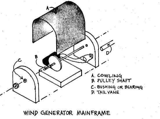
1) Lay out the main frame base and end plates on 3/4" wood and cut out with a band saw or jig saw. Carefully align the end pieces and drill the shaft bushing hole to fit the brass tubing tightly. Slide 1" sections of brass tubing into the end plates and secure with epoxy. Ball bearings could be mounted in a similar fashion. Assemble the frame with wood screws and glue. Cut and bend the cowling to cover the chassis neatly. Hold cowling with small screws.
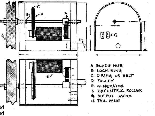
2) Thread the first 2 inches of the shaft with a 10-24 die. Fashion wood pulleys from 3/4" stock and file the edge to match the O ring thickness. Slide the shaft into the chassis with pulleys in position. Lock the pulleys with screws. Turn the shaft with a power drill and hold a hack saw against the shaft to saw a shallow notch to receive the lock ring. Fashion a smaller pulley for the motor from 1/2" dowel. Attach the motor to the base with 0 ring in place and adjust its position until the shaft will turn the motor with a minimum of friction.
3) Remove the wheel from a ball bearing caster. Cut a 1" x 1" wood strip with a rounded end, drill a hole to match the caster axle. Glue and screw the wood strip to the base of the chassis. The entire chassis should now be able to pivot to a vertical position.
4) Slide a section of 1/2" dowel on the shaft off center. Mount the microswitch on the rear main frame plate with screws, and adjust it carefully so that the eccentric dowel will trip the switch once each turn. Mount two prong jacks in the rear plate; connect the microswitch to one and the motor output to the other.